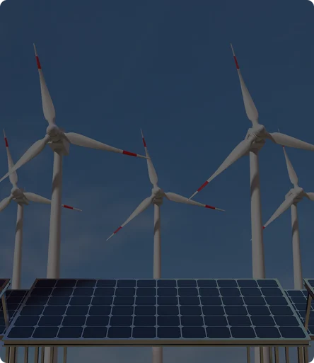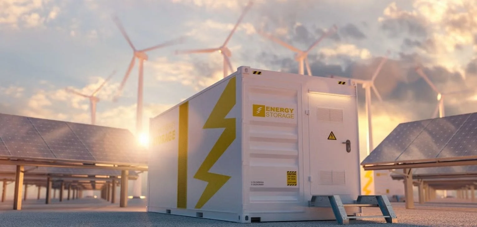
For over a century, the global energy framework operated on a simple model: big power plants generated electricity exactly when people needed it. Because we couldn’t store power, everything had to be perfectly balanced in real-time. Today, that old system is changing. As we switch to a modern, decentralized grid, we can no longer rely on those old machines for stability, making battery energy storage systems essential to keep the lights on.
The solution (and the defining asset of this decade) is the battery energy storage system (BESS). Many people see them as just “warehouses for electricity,” but they are much more than that. A BESS is actually a sophisticated digital-to-chemical conversion engine. These systems provide the agility required to manage a grid that no longer relies on predictable fuel, but on the shifting patterns of the natural world. Integrating energy storage technology allows us to bridge the gap between generation and demand.
By using a combination of hardware (BMS, PCS) and AI-driven software, an energy storage system balances grid frequency, manages peak demand, and generates revenue through market arbitrage. As the energy transition accelerates, BESS has become the essential tool for maintaining a stable, decarbonized, and high-performance power grid.
This guide is written for energy asset owners, utilities, developers, and trading teams evaluating storage assets for grid-scale deployment.
What is a Battery Energy Storage System (BESS)?
A Battery Energy Storage System (BESS) is a grid-connected infrastructure asset that stores electricity in chemical form and redispatches it via inverters to provide frequency regulation, peak shaving, energy arbitrage, and reserve capacity.
By integrating batteries, inverters, and intelligent software, a BESS provides grid stability, frequency control, and cost optimization.
Unlike high-speed discharge components like capacitors, a BESS is engineered for endurance and high-volume throughput. It serves as a critical “dispatchable energy resource,” effectively unlinking the timing of power production from the moment of its actual utilization.
While the phrase “battery energy storage” is frequently used as a synonym, the term “system” highlights the true complexity of the technology. A standalone battery is merely a passive container; conversely, a BESS represents a harmonized integration of physical hardware and intelligent software logic. This digital architecture acts as the asset’s ‘command center,’ regulating the speed of energy intake and discharge to protect the battery system from wear and tear while maintaining perfect synchronization with the wider electrical network.
Main Classifications of Battery Energy Storage Systems (BESS)
Not all BESS projects are the same. They are designed based on where they connect to the grid, how they are used, and what technology is inside. Here are the most common ways to classify these systems:
1. Grid Location: FTM and BTM
BESS are classified based on where they connect to the electrical grid and who they primarily serve.
- Front-of-the-Meter (FTM): These are large, utility-scale systems connected directly to the power grid. They help grid operators balance the energy supply for entire cities or regions.
- Behind-the-Meter (BTM): These are installed on the customer’s side (at a factory, business, or home). Their main goal is to manage local energy costs, provide backup power, and optimize solar energy use.
2. Operational Purpose
Systems are also designed based on the specific technical problem they are meant to solve:
- Power-Oriented Systems: Built for “agile” applications like frequency control and voltage regulation. They are designed to react in milliseconds.
- Energy-Oriented Systems: Optimized for long-term storage tasks like energy arbitrage (buying low, selling high) and shifting heavy energy loads to different times of the day.
3. Battery Chemistry and Technology
A BESS project is ultimately defined by its internal chemistry and cell technology. These factors shape the system’s DNA, controlling critical variables such as safety, energy density, and long-term performance retention over thousands of cycles. Main battery chemistries are:
- Lithium-Ion LFP (Lithium Iron Phosphate): This technology is used in more than 80% of large-scale storage projects today. It has a very low risk of fire and maintains its performance even after thousands of charge cycles. Since it contains no cobalt, it is the ideal solution for those looking for an eco-friendly and long-lasting investment.
- Lithium-Ion NMC (Nickel Manganese Cobalt): These can store much more energy in smaller spaces compared to LFP. While advantageous for projects with space limits, they tend to heat up more during operation and require advanced, high-precision cooling systems.
- Vanadium Redox Flow Batteries: Unlike traditional batteries, these store energy in massive liquid tanks. Their biggest advantage is providing continuous power for 10 to 12 hours. They do not lose capacity over a lifespan of more than 20 years, making them essential for very large utility-scale investments.
- Sodium-Ion (Na-ion): This technology uses sodium (salt), which is much more abundant and cheaper than lithium. Although it is a newer technology, it is seen as a strong rival to lithium due to its low cost and durability in cold weather conditions.
- Zinc-Based and Solid-State Technologies: These are developing technologies that do not contain flammable materials. They are often preferred in urban areas or buildings where fire safety is the highest priority.
4. Service and Discharge Duration
This defines how long the system can provide its full energy capacity:
- Short-Duration: Usually designed for 30 minutes to 2 hours of storage. These are used for fast grid stabilization and balancing services.
- Long-Duration (LDES): These systems provide 6 hours or more of discharge capacity and act as a strategic energy reserve for the power grid.
What are the Components of a Battery Energy Storage System?
A battery energy storage system consists of interconnected hardware and software subsystems that manage energy storage, safety, and grid interaction. Each component plays a vital role in transforming a chemical battery into a reliable power plant.
Battery System (Cells, Modules, and Racks)
This is the physical storage core of the project. Energy is stored electrochemically in individual cells, which are grouped into modules. These modules are then stacked into high-voltage racks. This hierarchical structure allows the system capacity to be scaled according to the specific needs of the grid or facility.
Battery Management System (BMS)
The BMS acts as the system’s security shield. It monitors cell voltage, temperature, and State of Health (SoH) with millisecond precision. By balancing the energy between cells, it prevents uneven wear and tear. In the event of a technical risk, the BMS physically isolates the system to ensure maximum safety.
Power Conversion System (PCS / Inverter)
Batteries operate on Direct Current (DC), while the power grid uses Alternating Current (AC). The PCS is the bidirectional bridge between these two worlds. It converts grid power for charging and transforms stored energy into high-quality AC power for discharge back into the grid at the correct frequency.
Energy Management System (EMS)
The EMS is the “centralized control layer” of the BESS. It coordinates communication between all hardware components and implements operational strategies. It decides exactly when and how much power the system should provide, ensuring all assets work in perfect harmony.
Thermal Management (HVAC and Liquid Cooling)
Battery performance and lifespan are directly linked to temperature. Industrial-grade HVAC or liquid cooling solutions keep the cells within their ideal operating range. This prevents heat-related capacity loss and ensures the system remains efficient even under heavy loads.
Fire Suppression and Safety Systems
Critical for industrial safety, these systems include gas detection sensors that can identify flammable leaks instantly. Automated fire suppression, using aerosol or gas-based agents, is designed to stop potential risks at the source without damaging the electrical components.
Grid Connection and Protection Equipment
This is where the system physically and safely connects to the grid. It includes transformers to step up voltage, along with circuit breakers and isolators. These components protect the facility and the grid from electrical faults by isolating the system during emergencies.
Integration and Trading Software (Optimization Layer)
This is the commercial brain that determines the project’s return on investment. Platforms like smartPulse pull real-time market data to analyze price trends. The software optimizes charge and discharge cycles to maximize revenue from market participation and arbitrage.
| Subsystem | Primary Function | Business Impact |
|---|---|---|
| Battery System (Racks) | Energy Storage | Determines total capacity and discharge duration (MWh). |
| Battery Management System (BMS) | Safety and Balancing | Protects cell health and slows down capacity degradation. |
| Power Conversion System (PCS) / Inverter | AC/DC Conversion | Enables grid interaction and instant power output. |
| Energy Management System (EMS) | Operational Control | Coordinates all onsite components for higher efficiency. |
| Thermal Management | Climate Control | Prevents overheating and stabilizes system efficiency. |
| Fire and Safety | Risk Mitigation | Ensures facility safety and manages insurance compliance. |
| Grid Equipment | Transformation and Protection | Ensures safe physical connection to the utility network. |
| Power Trading Software | Revenue Optimization | Maximizes ROI by automating market participation. |
How Does BESS Work?
A Battery Energy Storage System (BESS) functions as a high-speed energy buffer for the electrical grid. It operates through a continuous, four-stage cycle that converts, stores, and redistributes power based on real-time demand.
The Capture and Conversion Phase (Charging Battery)
The cycle begins when the system receives surplus electricity from the grid or a renewable source, like a solar farm. Because the grid operates on Alternating Current (AC) but batteries can only store Direct Current (DC), the energy must be translated.
- The Power Conversion System (PCS), or bidirectional inverter, pulls AC from the grid and converts it into DC.
- This conversion happens at millisecond speeds, allowing the system to “soak up” excess power the moment it is generated.
The Electrochemical Storage Phase
Once converted to DC, the electricity is pushed into the battery cells. This initiates an electrochemical reaction where ions move between internal electrodes (typically through a liquid or solid electrolyte) to “park” the energy in a stable chemical state.
- While the energy is stored, the Battery Management System (BMS) acts as a real-time monitoring system. It monitors the “health” of every cell, ensuring they stay at the correct voltage and temperature to prevent wear and tear.
- Auxiliary systems, like liquid cooling or HVAC, maintain an ideal internal climate to prevent the batteries from overheating or aging prematurely.
The Intelligence Layer (System Management)
The system does not just sit idle while full. The Energy Management System (EMS) (the system’s brain) continuously listens to signals from the power market and the grid operator.
In utility-scale deployments, dispatch commands originate from Transmission System Operators (TSOs) or Distribution System Operators (DSOs). The EMS receives these grid signals and translates them into real-time charge and discharge instructions, allowing BESS assets to participate directly in frequency regulation, congestion management, and reserve markets.
- It monitors Grid Frequency: If the frequency drops (meaning there is too much demand), the EMS prepares to discharge.
- It monitors Market Prices: If prices are low, it stays in “charge” mode; if prices spike, it prepares to sell.
- It manages the State of Charge (SoC): Ensuring the battery never gets too empty or too full, which optimizes the asset’s lifespan.
The Dispatch and Synchronization Phase (Battery Discharging)
When the grid requires a boost or prices hit a profitable peak, the discharge cycle triggers. The chemical reaction inside the battery reverses, releasing a flow of DC power.
- The PCS converts this DC back into AC.
- Crucially, the inverter synchronizes this power perfectly with the grid’s current voltage and frequency (e.g., 50Hz or 60Hz) so it can be injected seamlessly.
- This response is nearly instantaneous, often providing full power in less than a second to stabilize the network and prevent blackouts.
What is C-Rate in Battery Energy Storage Systems?
C-rate defines the relationship between battery power and capacity in a Battery Energy Storage System. It indicates how fast a battery can be charged or discharged relative to its total energy capacity and directly determines system sizing, duration, and usable power.
C-rate is used for three different purposes in energy sector, which causes confusion. Therefore, it is good to understand all three usages independently.
Power-to-Capacity Ratio
It describes the ratio of applied power to battery capacity.
The phrase “X capacity at 0.2C” from a battery manufacturer, implies that if you buy a 100 MWh battery from this manufacturer, you will get 100 MWh capacity when you apply 100*0.2= 20 MW power to this battery over 5 hours, and if you buy a 50 MWh battery, you will get 50 MWh capacity when you apply 50*0.2=10 MW over the same period. Therefore it is good to define your capacity according to your planned maximum power since different C-rates will end up with different battery capacities.
Installation Configuration and Duration
C-rate is also used to describe battery duration. This is a direct ratio of battery capacity to battery power.
If you request a 100 MW battery with a C-rate of 1C from your battery systems supplier, this configuration can deliver 100 MW power for a total of 1 hour (approximately 100 MWh). If you request a 100 MW capacity battery with a C-rate of 2C, approximately 200 MWh is stored in the battery for a max instant power of 100 MW over the same period.
In the same way, this usage is also used as battery “duration”. A 2-hour battery is 2C, meaning a battery configuration that can deliver the amount of installed power for two hours. This usage simplifies the process because instead of specifying capacity and power separately, the duration of the maximum power needed is given, allowing the battery supplier to determine its own battery capacity based on its losses.
For example, if you want a power of 100 MW for a duration of 2 hours, a supplier with a low power loss product (let’s assume a 5% loss) could supply a battery with a capacity of 210 MWh, while a high power loss product supplier may offer a battery with a capacity of 220 MWh (10% loss). Usually in this use case the C-rate is not below 1 (it should not be for lithium-ion configurations).
Battery Chemistry Capability
The third usage reflects battery chemistry limits. It signifies battery chemistry by indicating the ratio of the maximum power that can be instantaneously drawn from the battery to the battery capacity.
For example, since high torque is desired in electric vehicles, battery chemistries here can go up to 8C-10C. For grid scale batteries, 1C batteries are generally used, but 2C can also be used in specific cases.
Key Battery Parameters Used in BESS Modeling
In practice, the first stage of any Battery Energy Storage System (BESS) investment is defining the algorithms that determine under which conditions the battery should charge or discharge. Once this operational use case is established, the next step is selecting battery technology, capacity, and power to meet these requirements and validating performance through simulation.
To ensure the system meets your specific operational goals, any purchase agreement should define BESS performance. While looking for to purchase a battery, following statements should be made “X kWh capacity when charged at K C power, allowing charging/discharging up to Y C, Z% cycle efficiency, minimum number of cycles B at an average A% DoD until T% End-of-Life capacity” to achieve expected results.
Battery Capacity:
Defines the amount of DC energy loaded into the battery when the battery is (usually) charged with the power specified by the battery manufacturer (indicated by C-rate).
In case of discharge, energy can be withdrawn from the battery with a loss equal to the cycle efficiency. Therefore, if the energy to be drawn from the battery defines the battery, these two parameters should be used to calculate the DC energy to be drawn from the battery.
Battery Power:
Represents the maximum charge and discharge power. Inverter sizing and battery chemistry must support this value without accelerating degradation.
For battery suppliers, battery power is the name given to the maximum amount of power allowed without causing an extra reduction in the life of the battery. Usually, this amount is given as a multiple of the battery capacity.
For grid-level energy storage applications, all batteries generally allow 1C to charge-discharge, while batteries that allow 2C to charge-discharge are available for an extra charge. In most battery configurations, the battery capacity is higher than the inverter power. That means, the maximum power that can be drawn is below 1C. For example, for a 6 MWh — 2 MW battery C-rate is 0.33C and a generic battery can provide this power. In an opposite configuration (if inverter power is greater than battery capacity), a special battery must be purchased or the maximum power to be taken from the inverter must be limited (such as 125 kW — 105 kWh) since required C level is above 1.
State of Charge (SoC):
The ratio of the total amount of energy charged in the battery to the total capacity of the battery at the instant the data is read (%).
For all intents and purposes, this is the most used and tracked parameter in real-time storage applications. Also, calculating SoC according to the Use Case applied to the battery is the most important and crucial problem in simulations. Discharge powers when battery is about to fully discharged and charge power when battery is about to fully charged are limited by the Battery Management System. Therefore, it is necessary to consider the instantaneous SoC value while considering the maximum power that can be applied to the battery. In fact, “fast charge” term is defined by the limitation of Battery Management System. It is used to define the fastest charging amount that can be performed without this limitation.
State of Health (SoH):
This parameter is used to define the amount of energy that can be charged into the battery during operation in proportion to the battery capacity.
It is determined by scaling the nominal capacity with a starting assumption of a battery capacity at 100 units. For example, when a 150 kWh battery with an instantaneous SoH parameter of 80 is fully charged, the energy that can be charged into the battery can be calculated as 150*80/100 = 120 kWh. The energy that can be discharged from this battery is also calculated by multiplying 120 kWh by the cycle efficiency (%).
End-of-Life Capacity (EoL):
This parameter is usually used to define the end of lifecycle for batteries. It basically refers to the value of “State of Health” (SoH) parameter when the battery is no longer usable.
Number of Cycles:
A round of charging and then discharging a battery is referred to as a “cycle”. The minimum number of cycles that the battery can achieve during its life is usually provided together with the battery information, after which the battery is considered to have reached its End-of-Life Capacity. This number is often determined with a average Depth of Discharge (DoD) level.
Charge and Discharge Efficiency:
Represents energy losses during charging and discharging.
It is the ratio of the energy given to the battery (or drawn from the battery) to the energy stored in the battery (or discharged from the battery) during charging (or discharging). To store 100 units of energy in the battery, more than 100 units of energy must be supplied, and to supply 100 units of energy to the grid, more than 100 units of energy must be withdrawn from the battery. The ratios in this process constitute charging and discharging efficiency and are used as a parallel parameter with cycle efficiency.
Depth of Discharge (DoD):
The percentage of capacity used in a single cycle. Higher DoD generally reduces total cycle life.
For example, both decreases in the SoC parameter from 90% to 10% or from 100% to 20% equal to an 80% DoD. This parameter is also used to define the average SoC operating range over the life of the battery. Assuming that the battery is used at an average of 80% DoD gives a predictable estimate of the number of cycles that can be obtained from the battery, while using variable DoD creates uncertainty about the number of cycles.
Cycle Efficiency:
The ratio of energy discharged to energy charged during a full cycle that returns the battery to its initial State of Charge (SoC).
If this value is measured at the DC output of the battery, it is called DC cycle efficiency, and if it is measured at the grid connection point (AC output), it is called AC cycle efficiency. DC cycle efficiency is greater than AC cycle efficiency due to inverter losses, but AC cycle efficiency should be considered in feasibility calculations. The value given by the battery manufacturers is the DC cycle efficiency, the AC cycle efficiency can be calculated approximately according to the inverter efficiency to be used.
Typical BESS Project Development Timeline
While every storage project has its own technical and regulatory nuances, most grid-scale BESS deployments follow a similar development path—from early revenue modeling to full market operation.
- Use case definition and revenue modeling
- Grid connection application
- Technology selection
- EPC contracting
- Commissioning and compliance testing
- Market onboarding
- Operational optimization
Delays most commonly occur during grid approval and market integration — areas increasingly automated through digital energy platforms.
Common Failure Modes in BESS Projects
Despite rapid technological progress, many BESS projects underperform due to predictable technical and operational challenges that often emerge after commissioning.
- Thermal runaway events
- Inverter or PCS failures
- State-of-charge miscalculations
- Communication loss with TSOs
- Suboptimal dispatch accelerating degradation
Most commercial losses do not come from hardware defects but from operational inefficiencies and poorly coordinated market participation.
Financial Benefits of Battery Energy Storage Systems
A battery energy storage system is far more than a technical asset; it is a high-performance financial instrument. Its primary economic value lies in “Value Stacking”, the ability to participate in several energy storage solutions and revenue streams simultaneously, often within the same operating hour.
This versatility allows owners to maximize the return on investment (ROI) by dynamically shifting the battery’s activity to wherever it generates the most value.
High-Precision Grid Support (Ancillary Services)
The most profitable role for a BESS is providing “Frequency Response.” The electrical grid must maintain a constant frequency to function safely. If a power plant fails unexpectedly, the grid’s frequency can drop in seconds.
Unlike traditional gas plants that take minutes to ramp up, a BESS can detect a shift and inject full power in less than 100 milliseconds. Grid operators pay a high premium for this millisecond-speed reliability, making it a major revenue stream for BESS operators
Tactical Market Arbitrage
This is the classic “buy low, sell high” strategy applied to electricity. Using automated trading platforms like smartPulse, the system scans wholesale markets for price volatility.
When renewable production is high and demand is low, the power storage unit charges at a low cost. When the evening peak arrives and prices spike, BESS discharges. The “spread” between the purchase and sale price is the profit, making arbitrage a cornerstone of commercial BESS profitability.
Steady Revenue: Capacity Markets and System Readiness
In many energy markets, energy storage companies can secure a predictable income stream through what is known as capacity payments. Unlike arbitrage, which depends on price fluctuations, these payments are made to the asset owner simply for ensuring that the BESS is available and ready to discharge during periods of extreme grid stress.
This “readiness” ensures that even during rare, high-demand events (such as extreme weather or the failure of a major power plant), the grid has enough “Resource Adequacy” to prevent blackouts.
Infrastructure Deferral and Cost Avoidance
Energy utility companies frequently face a multi-million dollar dilemma: a specific neighborhood or industrial zone is growing faster than the local grid can handle. Traditionally, the only solution was a “wires-and-poles” project, a capital-intensive process of digging trenches, replacing transformers, and installing higher-capacity power lines.
A battery energy storage system provides a much faster and more cost-effective “Non-Wires Alternative” (NWA). By strategically placing a BESS at a congested substation or a stressed feeder line, utilities can manage local peaks without rebuilding the entire infrastructure.
Maximizing Renewable ROI
For investors of solar or wind energy projects, the battery prevents “curtailment”, where green energy is wasted because the grid cannot accept it. By storing that excess power and selling it later, the BESS ensures that every megawatt-hour generated by the renewable asset is eventually monetized, significantly improving the project’s overall financial performance.
Lifecycle Economics of Battery Energy Storage Systems
Beyond upfront CAPEX, project profitability depends on degradation, operational efficiency, and dispatch strategy. These factors are captured by the metric Levelized Cost of Storage (LCOS).
LCOS reflects total lifetime cost divided by delivered energy and is influenced by:
- Battery degradation rate
- Cycle efficiency
- Replacement planning
- OPEX and maintenance
- Revenue optimization strategy
Two identical batteries can exhibit radically different LCOS depending on how intelligently they are dispatched. Algorithmic control typically improves lifetime revenue by 15–30% versus manual operation.
How to Optimize and Automate BESS?
BESS optimization combines automation software, predictive analytics, and real-time market participation to maximize revenue and extend asset life.
To move beyond simple energy storage and enter the realm of high-performance asset management, a battery energy storage system must be treated as a dynamic digital entity. Physical hardware is only as effective as the logic driving it. By layering advanced power storing technology with intelligent software, operators can shift from reactive monitoring to proactive, automated wealth generation. Optimization and automation are the twin engines that drive the long-term profitability of any BESS.
Algorithmic Market Participation
Modern energy markets move at a velocity that exceeds human capability. To maximize BESS revenue, automation software like smartPulse executes “Algorithmic Trading.”
- Automated Bidding: The system continuously analyzes the Day-Ahead and Intraday markets, submitting bids automatically to capture the best price spreads.
- Multi-Market Co-optimization: A smart BESS doesn’t just look at one market. It automatically splits its capacity (for example, using 20% for frequency response and 80% for arbitrage) to ensure every megawatt is sold to the highest bidder.
Predictive AI and Forecasting
True optimization requires looking into the future. By integrating Artificial Intelligence into energy storage systems, operators can anticipate market shifts before they happen.
- Price Forecasting: AI models ingest historical data, weather patterns, and grid congestion reports to predict when prices will spike. This allows the BESS to charge during unexpected price drops and discharge during peak volatility.
- Renewable Synchronization: For renewable energy facilities, like bess solar sites, automation software predicts cloud cover and solar output, ensuring the battery is always empty enough to capture excess solar and full enough to cover evening demand.
Intelligent State of Charge (SoC) Management
Automation isn’t just about selling energy; it’s about protecting the asset. Managing the “State of Charge” is critical to preventing battery aging.
- Dynamic Setpoints: Instead of charging to 100% every time, an optimized battery might only charge to 80% if the market signals suggest that the extra 20% isn’t worth the accelerated battery aging.
- Automated Balancing: The system automatically manages the “depth of discharge,” ensuring the cells stay within their ideal chemical window, which can extend the life of the power storage unit by several years.
Autonomous Health and Safety Monitoring
A fully automated battery energy storage system acts as its own first responder.
- Predictive Maintenance: Rather than waiting for a failure, the system uses “Digital Twin” technology to compare real-time performance against an ideal model. If a module starts to drift, the system sends an automated alert for maintenance before a breakdown occurs.
- Automated Thermal Control: To prevent premature aging, the EMS automatically ramps up liquid cooling or HVAC systems based on forecasted discharge intensity, preparing the thermal environment before the battery even begins to work.
Virtual Power Plant (VPP) Integration
For energy storage companies managing multiple sites, automation allows for the creation of a Virtual Power Plant.
- Fleet Automation: A central “brain” manages hundreds of separate power storage systems as if they were one giant battery. This allows small BESS units to band together and participate in large-scale utility tenders that they could never access alone.
By implementing these solutions, the transition from a manual “battery in a box” to an autonomous, profit-generating power plant is complete. Automation doesn’t just make life easier; it is the fundamental difference between a BESS that merely survives and one that thrives in a volatile market.
Grid Compliance and Interconnection Requirements for BESS
Before a battery can participate in energy or ancillary markets, it must comply with local grid codes and interconnection standards defined by the Transmission System Operator (TSO) or Distribution System Operator (DSO).
- Protection relay coordination
- Voltage and frequency ride-through capability
- Reactive power control
- Black start readiness (where applicable)
- Communication integration with TSO systems
Failure to meet these requirements can delay commissioning by months. Modern projects increasingly rely on software platforms to validate dispatch feasibility before bids are submitted to market.

Working with smartPulse for BESS Operations
While the physical battery provides the capacity, smartPulse provides the intelligence that transforms it into a high-yield financial asset. Operating a BESS in today’s volatile energy markets requires more than just a connection; it requires a level of speed, precision, and foresight that manual management cannot achieve. Working with smartPulse bridges the gap between raw hardware and market-leading profitability through five key pillars:
End-to-End Market Integration
Navigating the complexity of multiple energy exchanges (such as Day-Ahead, Intraday, and Ancillary Services) is a massive operational burden. smartPulse offers a unified “Super Platform” that connects your assets directly to major TSOs and power exchanges (like Nord Pool, EPEX Spot, and EPİAŞ) from a single interface. This removes the need for fragmented software and ensures your BESS can bid into whichever market is most lucrative at that exact moment.
Fully Autonomous “smartBOT” Trading
Energy markets never sleep, and volatility can strike at 3:00 AM. The smartPulse smartBOTs are designed for 24/7 autonomous algorithmic trading.
- Speed: They react to price movements and grid imbalances in milliseconds, executing trades faster than any human operator.
- Accuracy: By automating the bidding process, smartPulse eliminates the risk of human error, ensuring your power storage system never misses a profitable spread or a critical grid-balancing event.
Advanced Digital Twin Simulations
Before committing your energy storage system to a specific strategy, smartPulse allows you to “test-drive” your operations. Using the BESS Digital Twin, you can simulate different market scenarios using real historical data.
- Pre-Investment: Perform highly accurate feasibility studies to see how a battery would have performed under past market conditions.
- Operational Tuning: Continuously refine your charging and discharging logic to ensure you are maximizing ROI without causing unnecessary wear and tear on the cells.
Asset Health & Revenue Balance
Profitability is not just about the next trade; it’s about the next decade. smartPulse’s optimization engine considers the technical constraints of your hardware. By managing the State of Charge (SoC) and depth of discharge with extreme precision, the software protects the battery from premature aging. This balance of “aggressive trading” and “asset preservation” ensures your BESS remains a high-performing revenue engine for its entire intended lifespan.
Real-Time Operational Visibility
Whether you are managing a single site or a massive portfolio of 700 MWh+, smartPulse provides a “glass-box” view of your operations. Through a centralized dashboard and a native mobile app, you can monitor everything from real-time energy throughput and cell health to live commercial performance. This level of transparency gives energy storage companies the confidence to scale their operations while maintaining total control.
Energy storage operations may seem complex, but the right technology simplifies everything. If you would like to discuss how to operate your batteries at peak efficiency with our expert team, we would be happy to introduce you to our platform.
The Future of Electricity is Stored
Battery Energy Storage Systems are no longer passive infrastructure assets. They are active, software-driven grid resources that combine electrochemical storage, power electronics, and intelligent control systems to deliver flexibility, reliability, and economic value.
From frequency regulation and congestion management to energy arbitrage and renewable energy integration, modern BESS deployments operate at the intersection of physical hardware and digital optimization. Their performance depends not only on battery chemistry and inverter capacity, but increasingly on Energy Management Systems (EMS), real-time market connectivity, and automated control logic.
As power systems transition toward higher shares of variable renewable energy, BESS is becoming a foundational element of grid stability. When integrated with advanced power trading and optimization platforms like smartPulse, energy storage transforms from a standalone asset into an operational backbone of modern electricity markets—enabling asset owners to maximize revenue while maintaining full compliance with Transmission System Operator (TSO) requirements.
In this context, successful battery projects are defined less by installed megawatt-hours and more by how effectively storage assets are dispatched, optimized, and monetized across multiple grid services. The future of energy storage belongs to systems that combine hardware performance with intelligent software orchestration.